
5000w 2sc5200 2sa1943 Amplifier Circuit Diagram Pdf Free Elle Circuit
The most commonly used type of power amplifier configuration is the Class A Amplifier. The Class A amplifier is the simplest form of power amplifier that uses a single switching transistor in the standard common emitter circuit configuration as seen previously to produce an inverted output. The transistor is always biased "ON" so that it.
Simple 100W HiFi Audio Amplifier Circuit Diagram Electronic Circuits Diagram
2 Amplifiers Schematic (±5-V Power Supply). and listening environment. Figure 1 shows the typical block diagram of an audio reproduction hardware system, which converts the digital audio source to the voltage signal that. amplifier, and external circuits. For resistor matching, 0.1% precision thin-film feedback resistors are recommended..

Tda7294 Amplifier Circuit Diagram Pdf 100 Watt Amplifier Circuit TDA7294 PCB imagens
Amplifier circuits form the basis of most electronic systems, many of which need to produce high power to drive some output device. Audio amplifier output power may be a nything from less than 1 Watt to several hundred Watts. Radio frequency amplifiers used in transmitters can be required to produce thousands of kilowatts of output
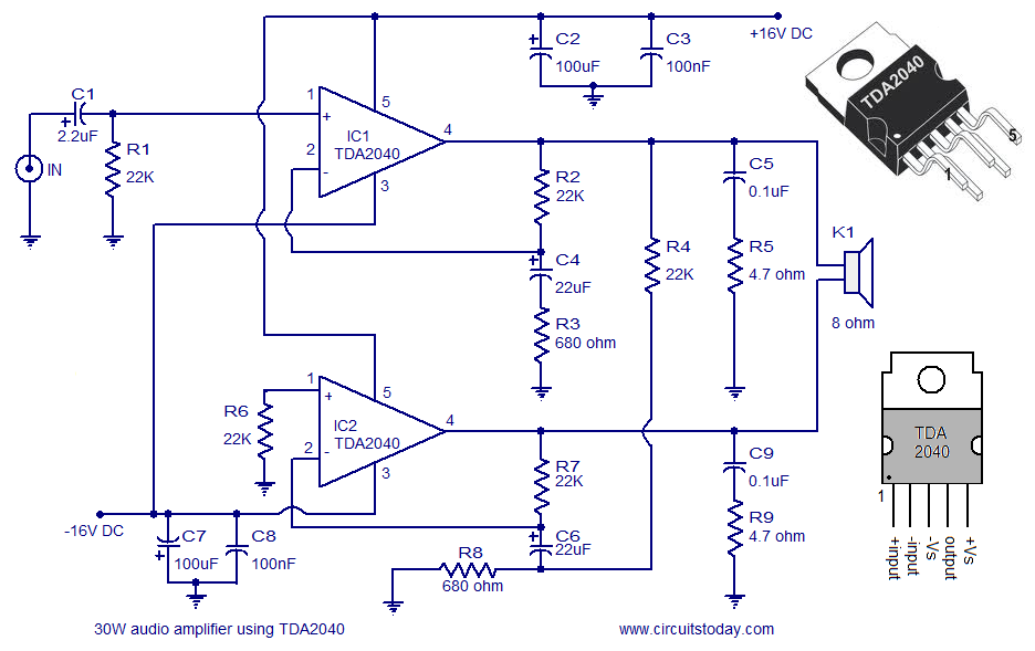
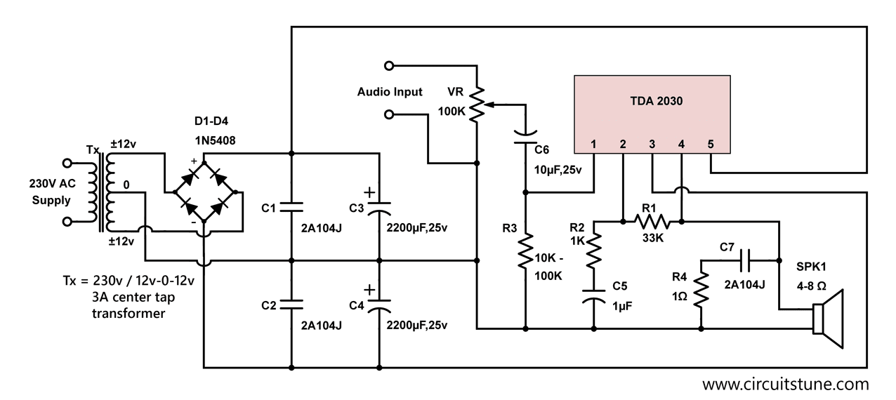
[Download 40+] Circuit Diagram Of Amplifier Using Tda2030
The common emitter amplifier circuit is the most often used transistor amplifier configuration. The procedure to follow for the analysis of any amplifier circuit is as follows: Perform the DC analysis and determine the conditions for the desired operating point (the Q-point) Develop the AC analysis of the circuit. Obtain the voltage gain.

Pin di Screenshots
• Describe typical tone control circuits. Section 4.3 Amplifiers and Impedance. • Describe typical circuits for controlling impedance. Section 4.4 NFB Quiz. •• Test your knowledge & understanding of impedance and tone control in audio amplifiers. Modified Response Curves
Power Amplifier 2000 Watt Circuit Scheme
A PDF file of a vintage book on practical amplifier diagrams, written by Robin and Lipman in 1947. Learn how to design and build tube amplifiers with quality, distortion, noise, and tone control in mind. A rare and valuable resource for tube enthusiasts and hobbyists.
New Audio Amplifier Circuit Diagram With Layout Pdf Wiring Diagram
Because of this, op amp input circuits are designed around a differential amplifier, also called an emitter-coupled amplifier or a long tailed pair, which provides the op amps two (inverting and non-inverting) inputs and also has the ability to cancel out voltage drift. Difference Amplifier The Op amp's basic operation is that of a difference
Electronic Schematic Circuit Diagram CircuitsTune
Chapter 1 of the Basic Linear Design handbook introduces the fundamentals of the op amp, a versatile and essential component for analog circuits. Learn about the op amp's history, characteristics, configurations, feedback, and applications. This chapter is a useful reference for anyone interested in analog devices and design.

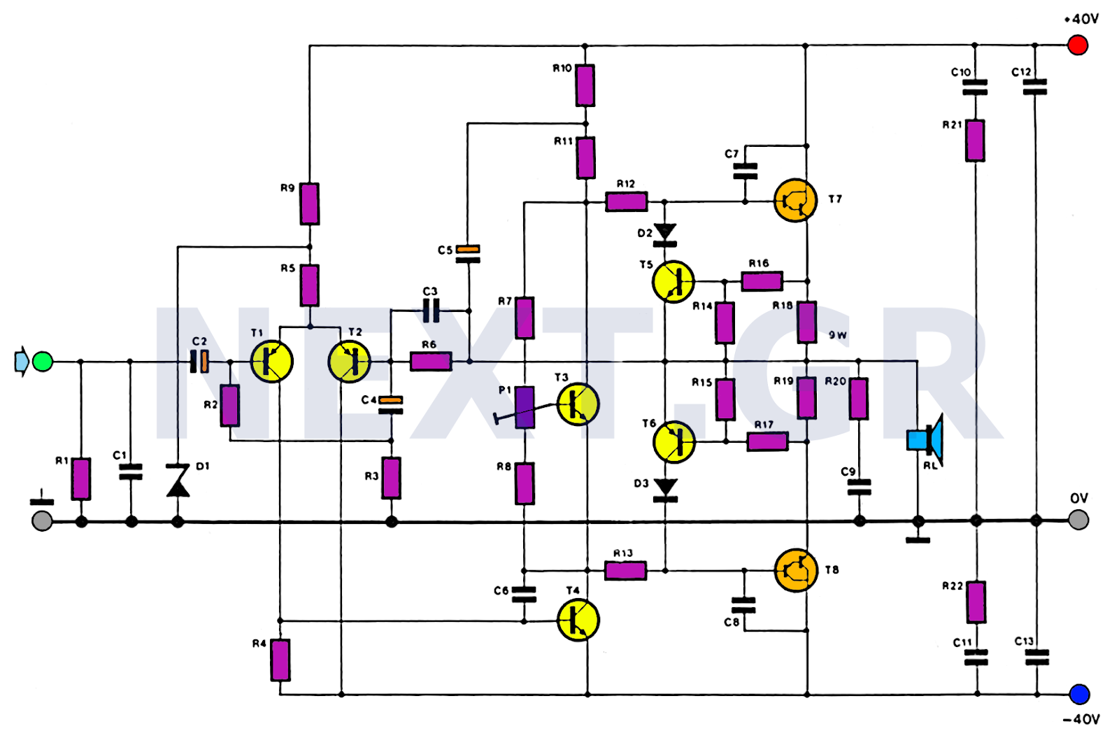
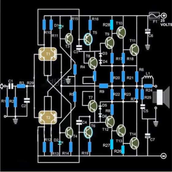
700W Power Amplifier with 2SC5200, 2SA1943 Electronic Circuit Subwoofer Amplifier, Speaker
An amplifier is used to increase the amplitude of a signal waveform, without changing other parameters of the waveform such as frequency or wave shape. They are one of the most commonly used circuits in electronics and perform a variety of functions in a great many electronic systems. The general symbol for an amplifier is shown in Fig 1.0.1.
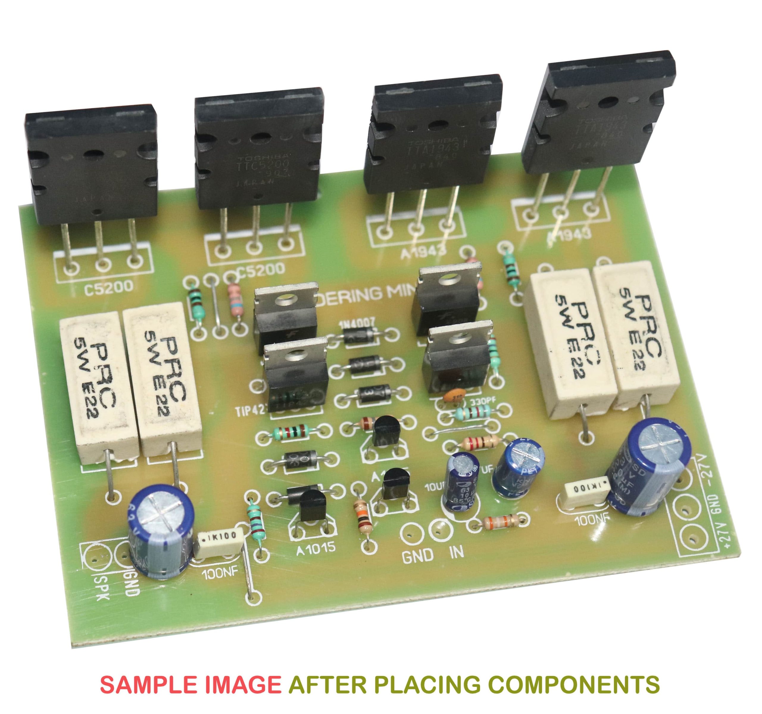
2sc5200 2sa1943 amplifier circuit diagram Soldering Mind
negative feedback around a high gain DC amplifier would produce a circuit with a precise gain characteristic that depended only on the feedback used. By the proper selection of feedback components, operational amplifier circuits could be used to add, subtract, average, integrate, and differentiate.

400W Audio Amplifier Circuit Diagram Pdf Fet400 Mosfet Amplifier Circuit 400w Electronics
Application Report AN-31 amplifier circuit collection ABSTRACT This application report provides basic circuits of the Texas Instruments amplifier collection.

Tda7294 Amplifier Circuit Diagram Pdf / 51 Amplifier Circuit Diagram Pdf Diagram The circuit
K. Webb ECE 322 4 BJT Amplifier Circuits Recall the two functional pieces of a BJT amplifier: Bias network Sets the DC operating point of the transistor Ensures the BJT remains in the forward-active region Signal path Biasing. Network Signal path Sets the gain of the amplifier circuit Significant overlap between the two parts
13+ D1047 Amplifier Circuit Diagram Robhosking Diagram
Description. The diagram shown here is of a 10W MOSFET audio amplifier circuit that requires only a single supply. Single rail supply is seldom used in Class-B power amplifiers. Anyway, for low power applications like this it's quite fine. Actually I got this circuit from an old cassette player that is still working and I am publishing it as it is.
.gif)
Simple 50W Electronic Amplifier Circuit Diagram Super Circuit Diagram
UNIT FUNDAMENTALS. The emitter terminal is common to the input and output signals of the common emitter (CE) transistor circuit. The ac output signal of a CE circuit is 180o out of phase with the ac input signal. After a base-emitter voltage (VBE) of about 0.6 Vdc, the base current (IB) increases very rapidly.
Kumpulan Skema Amplifier Mini Stereo dan Mono JandelaTV
1a Audio Amplifier Circuit Overview In the first part of lab#1 you will construct a low-power audio amplifier/speaker driver based on the LM386 IC from National Semiconductor. The audio amplifier will be a self-contained, battery-operated component.
2n3055 Transistor Amplifier Circuit Diagram Pdf
The equivalent circuit of this model is shown on Figure 9. R2 + + _ Vp Vn Vi Vo Ip In V in 1 I2 I1 R1 AVi Figure 9. Inverting amplifier circuit model Since our circuit is linear, the voltage at node 1 can be found by considering the principle of superposition. Vn is the sum of voltages Vn o and Vnin as shown on the circuits of Figure 10.